
Core Handling & Preservation
The Science
Starts at Surface.
From the moment the core reaches surface, our integrated workflow takes over. Six sequential operations — processing, scanning, photography, plugging, preservation, and monitored transportation — every step engineered to protect what the formation gave you.
Integrated Workflow
Six Steps from Lay-Down
to Laboratory Delivery
Step 01
Wellsite Processing & Stabilization
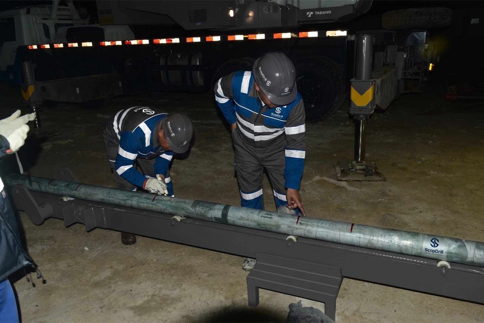
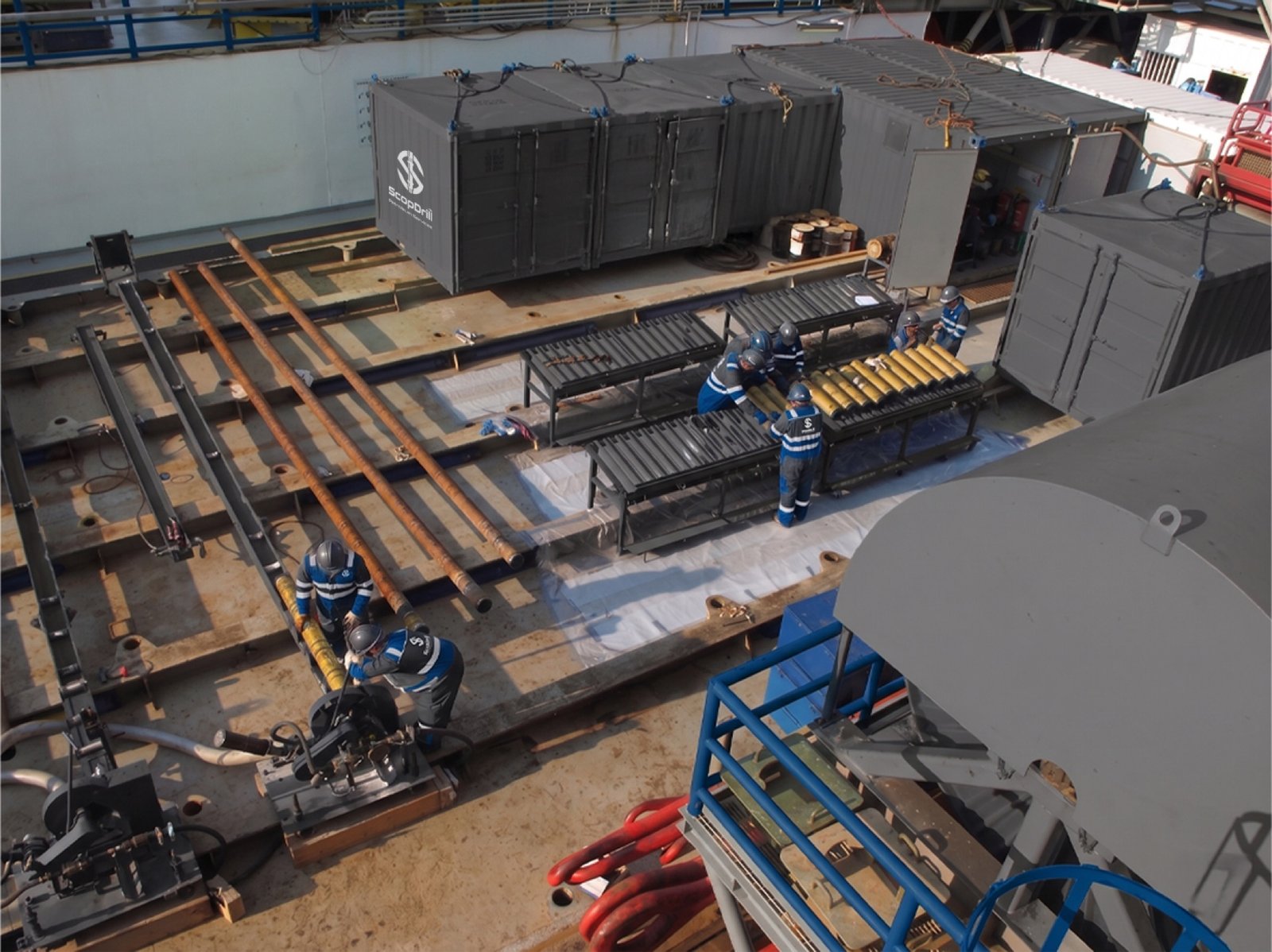
Immediate on-site handling and orientation upon retrieval. Inner tubes are laid down using the Lay Down Cradle, then cut into 1m (3ft) sections with a pneumatic air saw. Core stabilization prevents mechanical disturbance and structural alteration, maintaining in-situ conditions from the first moment of surface exposure.
Step 02
Gamma Ray Scanning
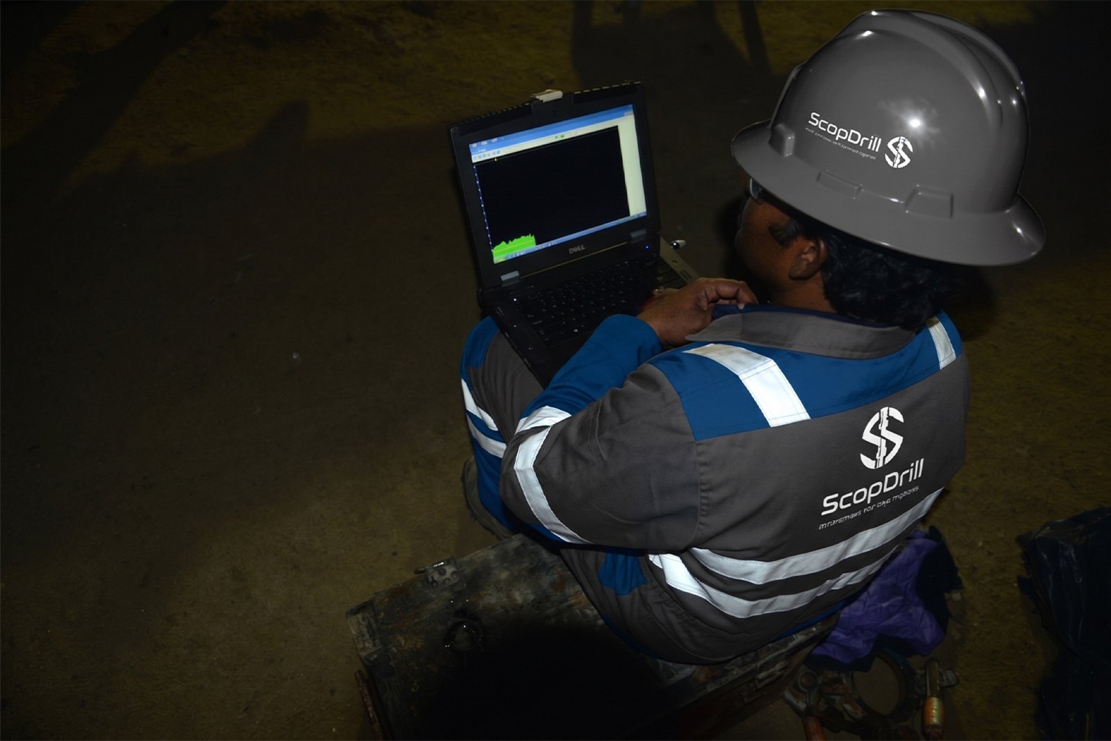
Core scanning using Gamma Ray logging for lithological correlation and depth matching. ScopDrill™ provides both Total and Spectral gamma ray scanning, enabling precise depth registration and formation correlation that ties the physical sample to the open-hole log suite.
Step 03
Core Photography & Digital Archiving
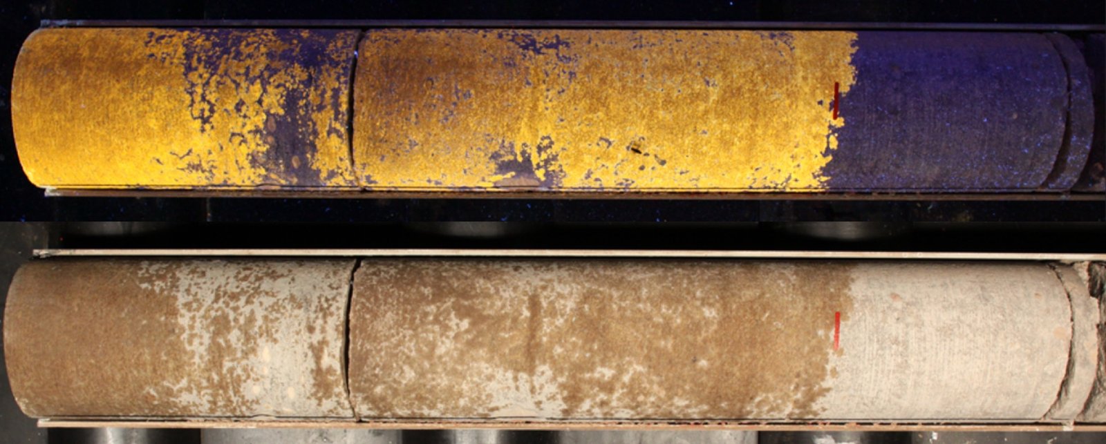
High-resolution imaging using the panoramic survey method in both White and UV light. UV photography reveals oil show locations invisible under standard illumination. All images are archived into a permanent digital dataset for advanced interpretation and future reference.
Step 04
Core Plugging & Sampling
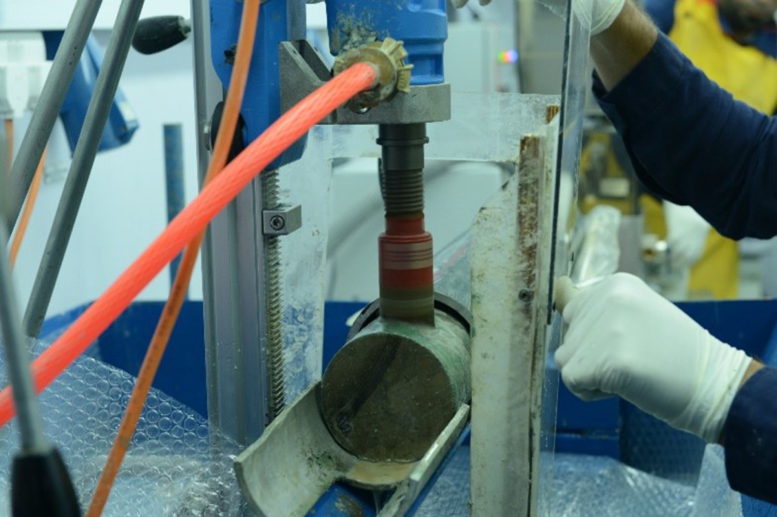
Precision core plugging for laboratory testing of porosity, permeability, and saturation. Representative sample selection ensures accurate petrophysical and geomechanical results that support reliable reservoir evaluation and completion decisions.
Step 05
Preservation & Protection
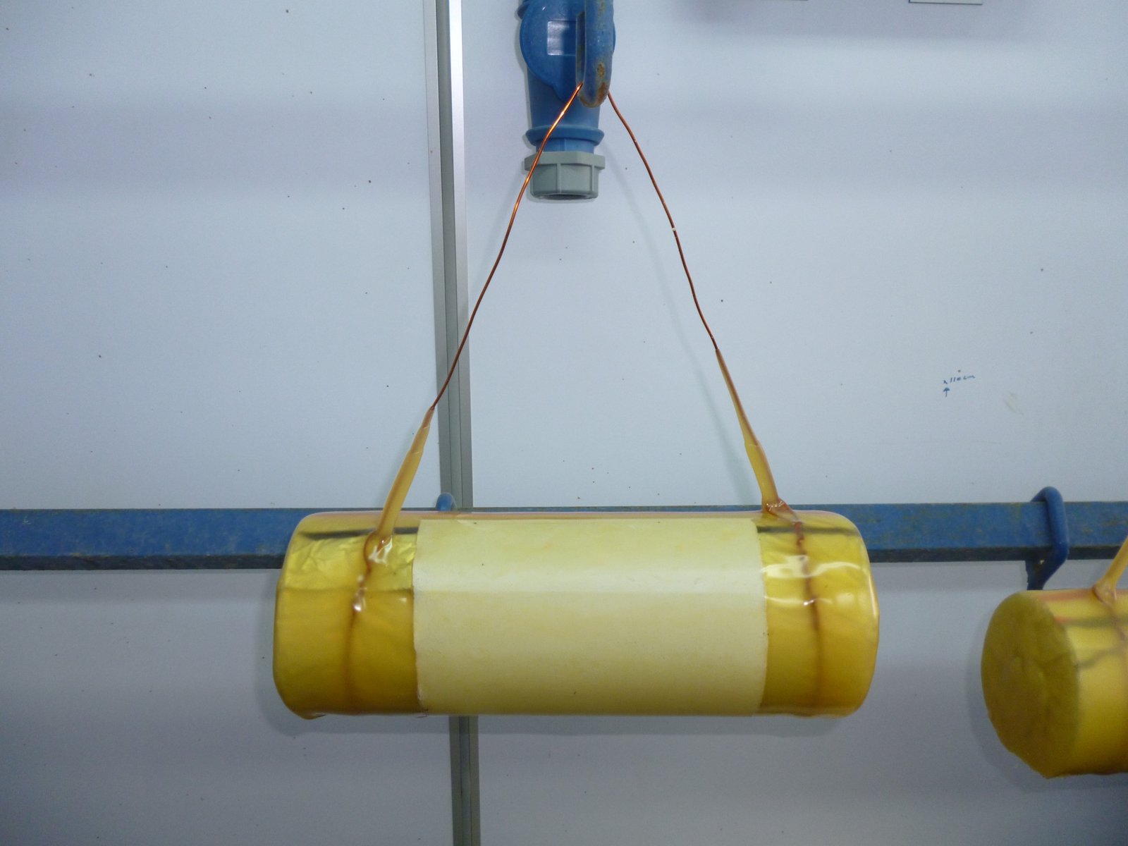
Advanced multi-method preservation: foam injection, epoxy resin, plastic strips, and gypsum stabilization, followed by waxing. Specialized packaging for fragile, fractured, and unconsolidated cores. Environmental control tailored to formation characteristics minimizes fluid loss, contamination, and oxidation.
Step 06
Transportation & Monitoring
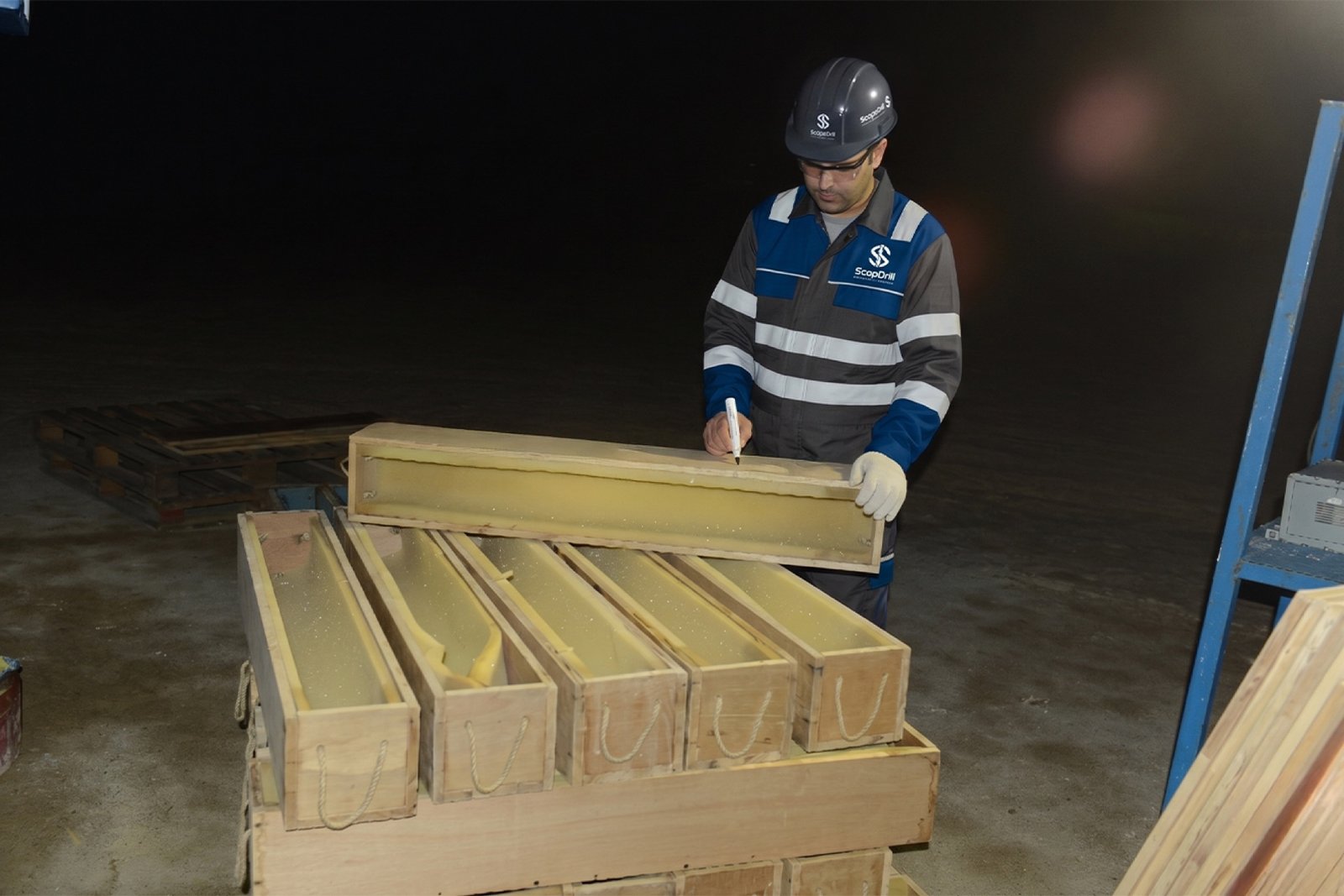
Secure transport from wellsite to laboratory using a specialized core container with deployed temperature, shock, and vibration record loggers. Full tracking and quality assurance ensures cores arrive in pristine condition, with complete handling documentation from field to facility.
Core Photography
Two Channels.
One Complete Picture.
White Light
Full-spectrum illumination for lithological detail, texture mapping, structural contacts, transitions, and faunal remains.
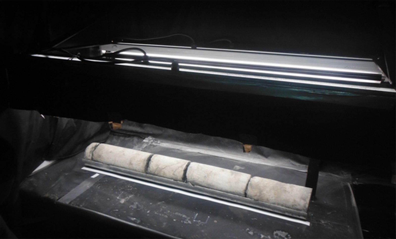
UV Light
Ultraviolet fluorescence locates hydrocarbon shows and residues invisible under standard white-light imaging.
Panoramic Survey Method
Core columns are photographed using the panoramic survey method, producing high-resolution continuous imagery for mineralogical and geochemical analysis. The method captures textures, structures, transitions, lithological differences, and faunal remains with precision that supports advanced interpretation and anchors the permanent digital archive.
Imaging Modes
White Light + UV, Both Captured per Run Interval
Method
High-Resolution Panoramic Survey Photography
Digital Archive
Permanent Dataset for Interpretation and Future Reference
Oil Show Detection
UV Fluorescence Indicates Hydrocarbon Locations in Core
Preservation & Protection
Multi-Method Protection
for Every Formation Type
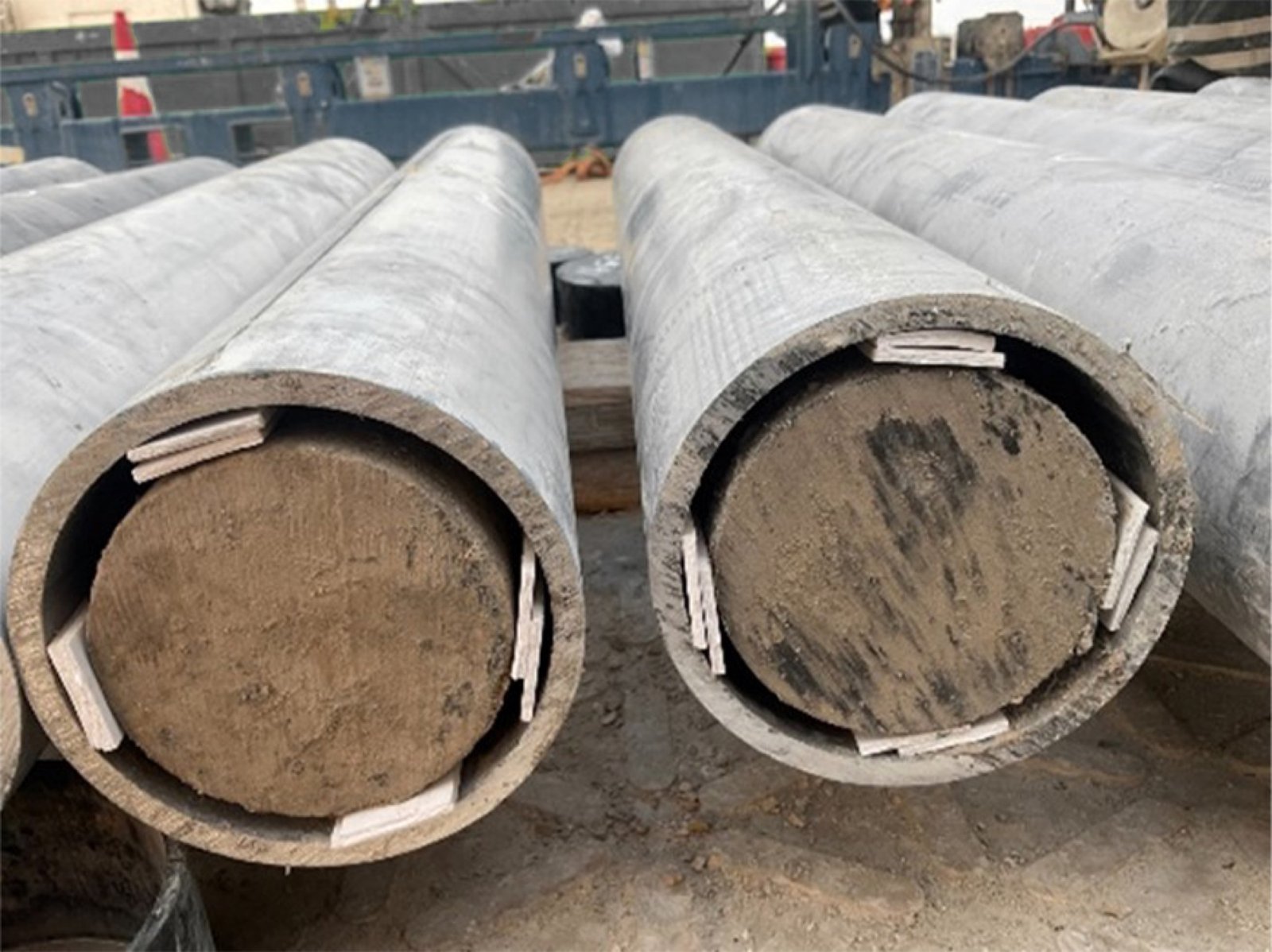
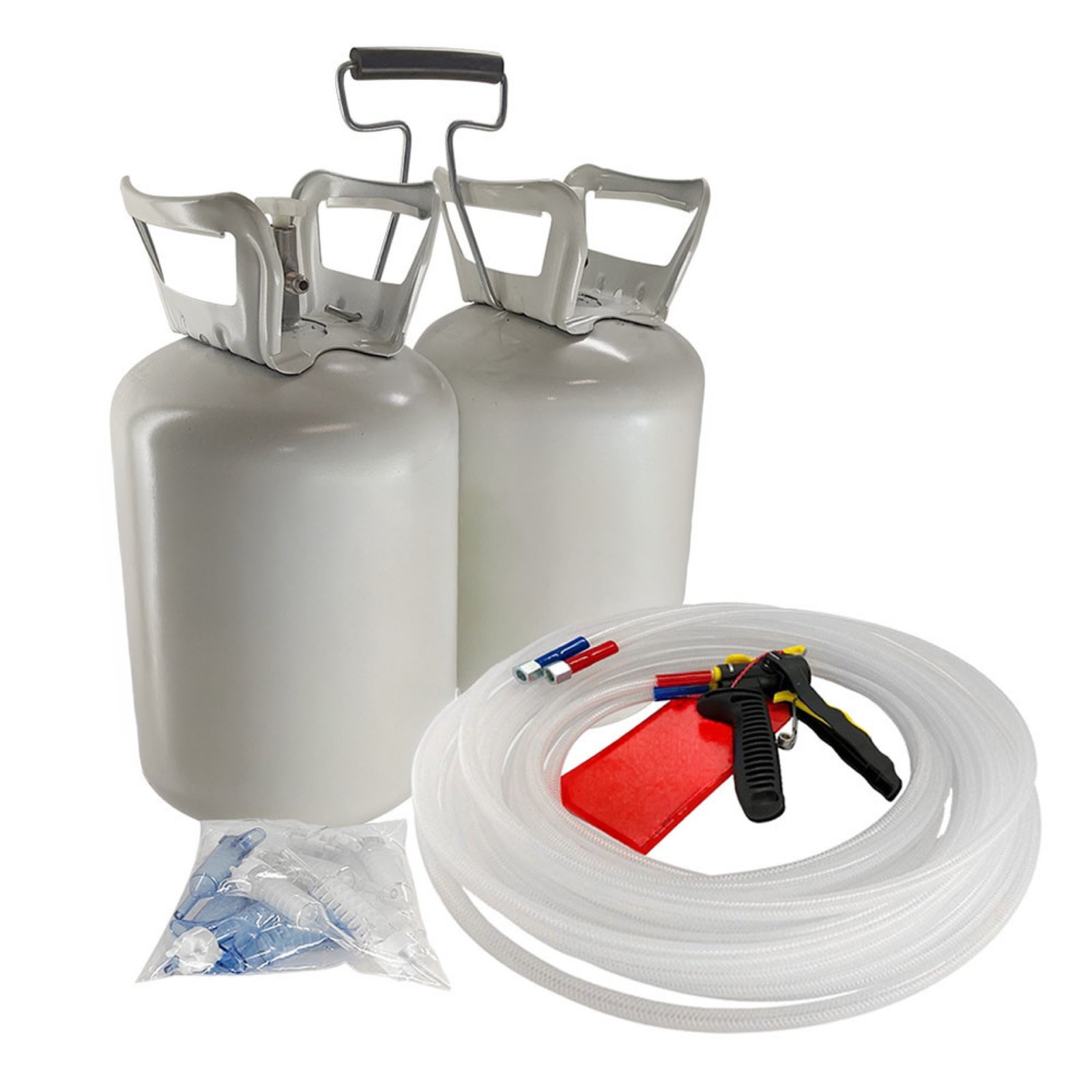
Preservation is a staged sequence, not a single step. ScopDrill™ applies each method in order: foam injection first to fill voids and prevent disturbance, followed by epoxy resin and plastic strips for structural support, gypsum for final containment, and waxing to seal against fluid loss and oxidation. The sequence is adapted to formation characteristics.
Stage 01
Foam Injection — Void Fill and Mechanical Stabilization
Stage 02
Epoxy Resin + Plastic Strips — Structural Reinforcement
Stage 03
Gypsum — Final Stabilization and Containment
Stage 04
Waxing — Fluid Loss and Oxidation Seal
Chain of Custody
Every Metre Tracked
from Wellsite to Lab
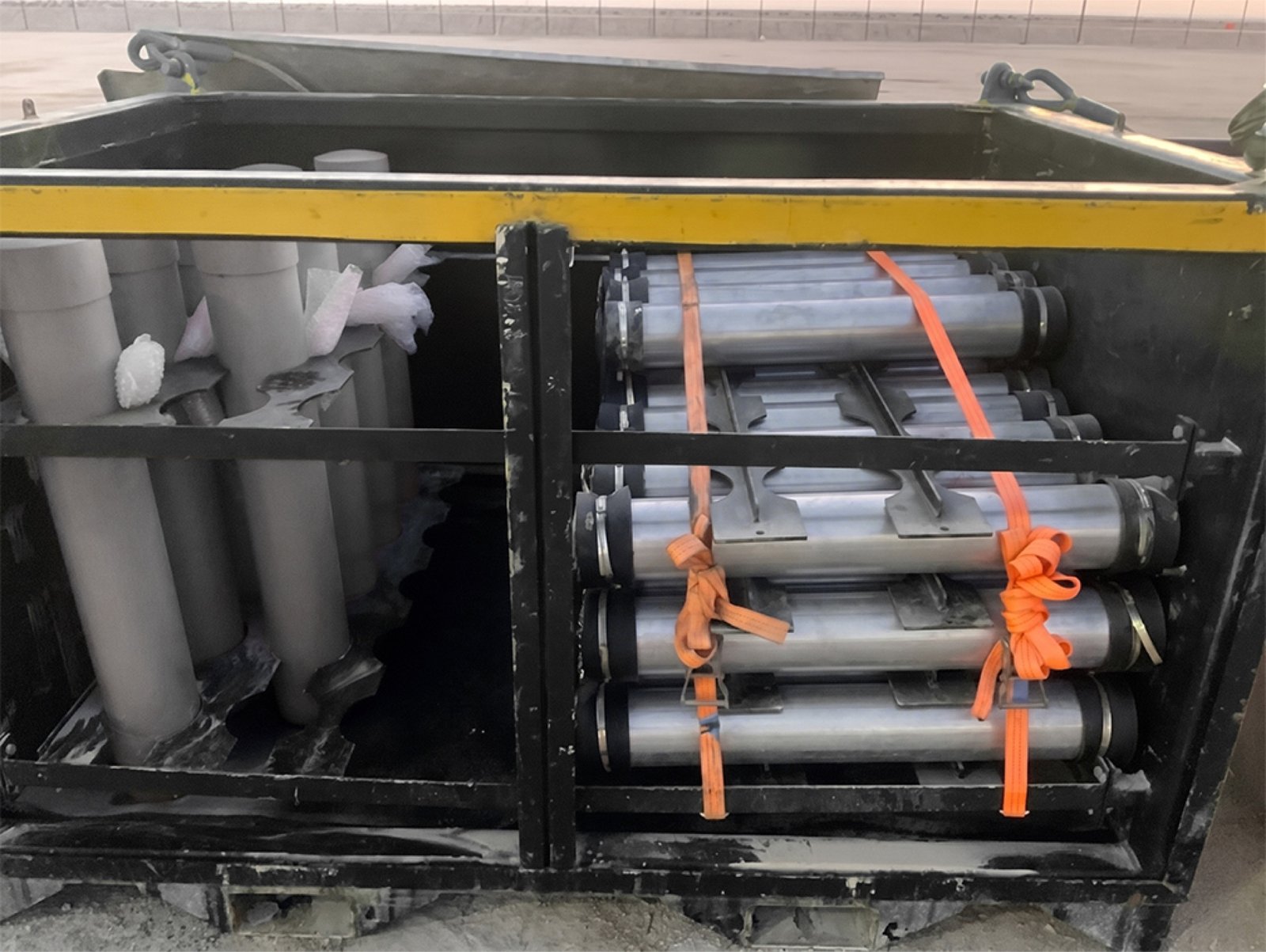
Specialized core containers with deployed instrumentation record temperature, shock, and vibration throughout the full transport chain. What left the wellsite is what arrives at the laboratory, documented with complete evidence. That certainty flows directly into the confidence of the reservoir model.
Container
Specialized Core Container, Purpose-Built for Secure Transport
Monitoring
Temperature, Shock, and Vibration Record Loggers Deployed
Tracking
Full Chain-of-Custody Documentation, Field to Facility
Outcome
Enhanced Confidence in Reservoir Modeling and Data Integrity
Contact Our Experts